|

|
Other information on this mount
|
|
|
Still, as this was a cheap mount and I didn't want to invest heavily, I looked into other low-cost possibilties for motorising. First, I investigated the number of worm wheel teeth on the RA-axis and found it had only 139 teeth (as compared to 144 teeth on my Vixen mounts). I had a spare Vixen SD-1 controller and Vixen MT-1 motor, but this combination was unsuitable due to the difference in worm wheel teeth (the SD-1 controller cannot be configured in any way). I also had a Vixen motor clutch, and it turns out the worm axis diameter is the same on the Astro-3 as on the Vixen (6mm). Somehow this should work....
Perhaps I could use the spare MT-1 motor with my MTS-3SDI controller ? This seemed like a good idea since the controller is configurable for a wide range of motors and mounts. The problem was then to buy or make a suitable cable between the controller and the MT-1 motor, plus adapt the motor to the mount. With some help and advice from my friend Øivind Tangen (thank you Øivind!), the cable was soon made and confirmed working!
|
The next step was then to configure the controller for the motor and number of teeth on the mount. With the help of a little Google research, I found that the MT-1 motor is really a Nippon Pulse Motor, model PF42-48I3. It has a step angle of 7.5degrees and an internal gearing of 1:120. From this information, plus the 139 teeth on the mount, I was able to calculate the parameters required for the MTS-3SDI controller, and upload the parameters from the PC to the controller. Quick tests showed that I could slew at 16x, but no faster (limitation of the MT-1). Whether it actually tracks at the correct speed remains to be seen, but I am quite confident.
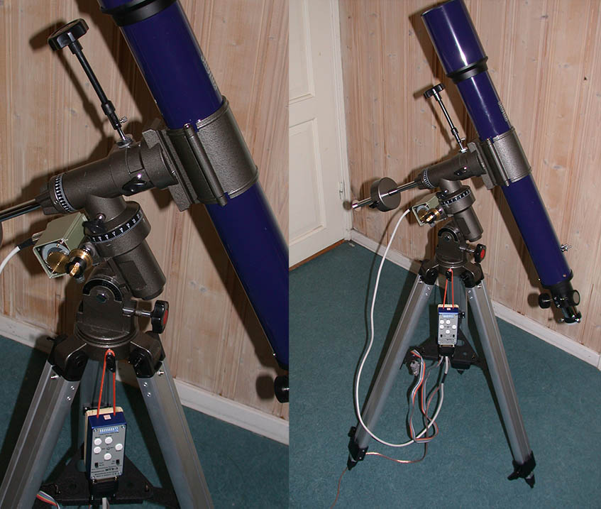
What remained, was to adapt the motor physically to the mount. I wasn't sure how to address this issue, but after some thinking I thought it would work by simply using a pair of flat steel bars and screw them to the mount using the existing screws that attach the worm assembly to the mount. This looked promising, but the motor spur gear could then not match with the clutch gear on the worm axis, as the worm axis was a bit too long, and the motor could not be moved sideways. So I cut the worm axis with a hacksaw about 4mm, and drilled a couple of holes in the MT-1 motor housing to attach it to the flat bars. The scrap bars I used were also cut to suitable lengths.
Interestingly, the mount has a threaded hole under the worm assembly (just over left bar in top left image below), and screwing in a machine screw in this hole makes a nice support helping to place the motor properly. With this setup, it all seems to be working! I just have to switch the RA motor direction (using a controller dip-switch), since two spur gears require the motor to step in the opposite direction compared to using the belt/pulley arrangement on the Vixen mounts. The mount can operate in all latitutdes, from 0 to 90 degrees, and there are no collisions between the motor and mount (the RA locking screw comes close, but does not collide with the motor). Previously, I had reversed the DEC worm, so the DEC worm axis no longer collides with the silver slow motion wheel on the RA axis (why was it made that way?)
Ready to measure the periodic error on this thing !

|
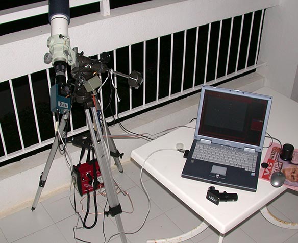
As the mount doesn't have a polar scope, I performed a simplified polar alignment procedure, similar to what one might do on a field trip. I first eyeball-aligned the mount and scope towards north, then set latitude to 60 (I live at 60 degrees north) and aligned the tube to be just over the motor. I then used the guide scope as polar scope and adjusted the mount in altitude and azimuth. To be more precise, one could follow up with drift alignment, but I didn't.
Next, after polar alignment, the scope was turned towards Rigel (Beta Ori) and the RA motor was switched on and the ToUcam webcam inserted at prime focus. The star was centered in the field ov view and exposure adjusted to make it a well defined dot on the screen. The next step was then to perform PEC training (PEC = Periodic Error Correction) using IRIS autoguiding and MTSca PEC autolearning . The worm period of this mount (with 139 teeth) is 616 seconds, and this is automatically recognised by MTSca via the controller configuration data. So I just had to let it run for 616 seconds. I used 200 msec agressivness (i.e. how long the buttons are pushed) as it seemed to be more effective than the default 100 msec.
The final phase was the actual measurements. I just let the scope follow Rigel for 3 worm periods. The first period was with PEC enabled in the MTS-3SDI controller. Clearly, the results are quite good, for well over 300 seconds the error is well below 10 arcseconds! After that it is clear that the correction has been incomplete, and error of 50 arcseconds remains. The reason is apparent by looking at worm period 2, which shows that the uncorrected error is more like 250 arcseconds peak to valley! Worm period 3 is again with PEC enabled, and it confirms the picture given by worm period 1.
In conclusion, the measured error is 250 arcseconds peak to valley, but there is hope for easy improvements here. First of all, it is possible to tune the mount mechanically much better than what I had done. Second, the MTS-3SDI controller can be tuned for higher agressiveness on the button push adjustments (MTS-3SDI "Corrfactor" parameter can be increased). Finally it is possible to tune the length of the putton pushes in MTSca. It should therfore be possible to reduce the overall error down to well below 20 arcseconds overall, perhaps lower. With such a result, wide field imaging is certainly possible with the ultra-cheap Astro-3 mount. Many thanks to Lidl! :-)

|
From the MTS-3SDI user manual: "The correction factor RA defines, how much the tracking frequency increases in SLOW mode when pressing the RIGHT-key, respectively decreases when pressing the LEFT-key (2.0 minus correction factor RA). There are 16 different adjustments form 1.0625 to 2.0000 possible."
Previously, I had used the default value 1.5 as correction factor, but it proved inadequate for this relatively large error. So I changed it to 1 + 15/16 = 1.9375. This new correction factor appears to be slightly on the aggressive side, but my theory is that it is better than being too modest. Due the way the PEC table works (with 32 control points and interpolations), any overcorrection will be effectively smoothed out.
From the graph below, it is obvious that these changes were effective. The graph is essentially flat when PEC is enabled, i.e. essentially all of the main periodic error has been cancelled by the Periodic Error Correction:

|
So how large is the residual error, and what does it look like? If we zoom in on the graph above, we can see a picture which isn't quite as pretty (see diagram below). The main variation is within 10 arc seconds (true, there are some larger, ugly spikes). The variations are quite fast and noisy, I believe they are mostly due to the imperfect shape of the worm. I am thinking that perhaps this could be improved by lapping the worm against the worm wheel using a drill.
But one interesting question could be this: Given a 10" accuracy on the tracking, what is the longest focal length that practically can be used with various cameras that would also fit in my travel luggage? Put slightly differently, what should my imaging travel scope look like? This table explores some possibilites:
| Camera | Pixel size [µM] | # of pixels [HxV] | Focal length [mm] | Speed | Pixel resolution [arcsec] | Field of view [deg] |
| Vesta SC3 | 7.4 | 640x480 | 200 | SLR lens | 7.6 | 1.35° x 1.0° |
| Vesta SC3 | 7.4 | 640x480 | 100 | SLR lens | 15.2 | 2.71° x 2.0° |
| Coolpix 995 | 3.45 | 2088x1550 | 31.0 | F5.1 | 22.29 | 12.7° x 9.5° |
| Coolpix 995 | 3.45 | 2088x1550 | 18.8 | F3.8 | 37.85 | 21.5° x 16.2° |
| Coolpix 995 | 3.45 | 2088x1550 | 8.2 | F2.6 | 84.27 | 47.9° x 36.0° |
All of these options seem possible, the 200mm with SC3 might be pushing things a bit, but my guess it should work if the lens isn't too slow, since the camera is quite sensitive. The Coolpix with its own lens should be ok at all focal lengths, and could be a reasonable wide field imaging device (while also being ok for normal holiday shots...).
Finally, it is interesting to note that without PEC, none of the imaging options above are usable, since the pixel resolutions are all smaller than the uncorrected periodic error. With PEC, they are all OK!

|
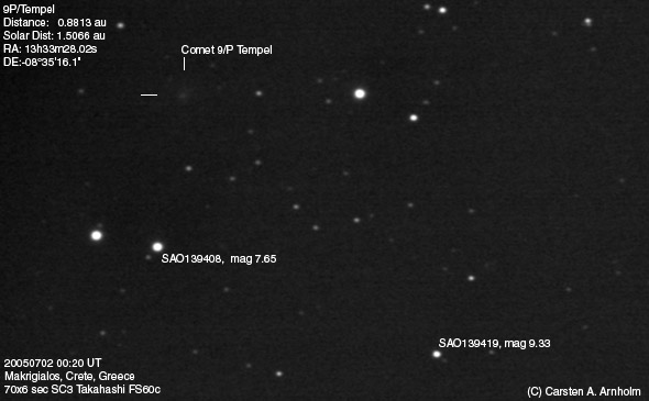
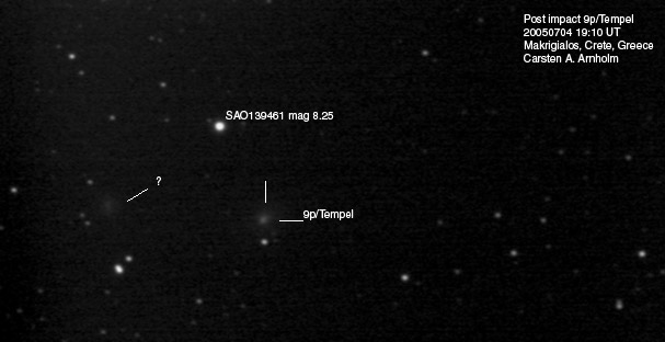
Imaging resultsI brought the Astro-3 and a Takahashi FS60c (354mm focal length F6) refractor to Makrigialos, Crete (Greece) in June/July 2005. It was a family holiday trip, but I managed to squeeze the mount and legs into a suitcase and carried the scope and laptop as hand luggage. On the way home I was stopped at the Iraklion airport and had to explain all the cables an things, but it went well.Using the SC3 camera and the FS60c on the hotel balcony, I was able to image the comet 9P/Tempel a day before and a day after the impact of the Deep Impact space probe. Pretty good for such a cheap mount I think.
|
|
|