For serious deep sky astrophotography is hard to do without autoguiding. But what is it really, why is it needed, and how can it be done using 2 webcams, one for imaging and one for guiding?
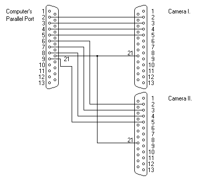
This article tries to explain some of the aspects involved with autoguiding and it goes on to explain how two long exposure webcams can be used for imaging and guiding while using only a single LPT port for controlling the long exposures of both cameras, using a simple home made LPT splitter box.

Wrong. There are many practical things that get in the way and which will ruin any long exposure photograph if you don't dig a bit deeper into the problem. For example, most equatorial mounts are driven by turning a worm wheel at the correct speed using a worm screw. But if the worm screw has an imperfect shape, the worm wheel will will not rotate at a constant speed, the rotation speed and therefore the RA speed will go up an down following a sine-like curve known as periodic error. It turns out that all mounts suffer from this problem, and eliminating it completeley requires a mechanical precision that is unavailable for a reasonable cost.
Other problems include imperfect polar alignment. It can be very hard to get it 100% right, and a slight error will introduce drift, most easily noticed in the DEC direction. Also, as your mount tracks across the sky, it points to different altitudes relative to the local horizon. This means that light reaching the telescope will be subject to differential refraction in the atmosphere, which will also cause a star to move in the field of view as the mount tracks.
In short, this is a difficult issue. But can we do anything about it? Yes.
The periodic error is the largest of the effects and it repeats itself every time the worm screw rotates, something that usually takes 8 or 10 minutes on most mounts. By measuring the error over such a period, it is possible to speed up and slow down the RA motor to counteract the periodic error. This method is called Periodic Error Correction, or PEC for short. It is often quite effective, but since it does not take all the effects into account, it is not a perfect solution.
Another method that can be used alone or together with PEC, is autoguiding. By measuring the drift of a guide star constantly as one images the sky, it is possible to counteract the measured effect before the drift ruins the image bu causing star trails. One way this can be done is to use two telescopes mounted in parallel and use one for imaging and one for measuring the tracking error using a dedicated guide camera. Using PC software, the measured tracking errors are automatically and immediately converted into guiding commands issued to the RA and DEC motors, such that the errors are kept at a minimum. This is what autoguiding is about. The nice thing about this method is that it corrects for all effects causing tracking problems. Of course, there are also unique problems with this method, but let us ignore that for now.
But in practice, there are some problems still. Most guide scopes are relatively small, and often there is no guide star bright enough in the field of view of the guide scope. A good solution then is to use a modified webcam as a guide camera and shoot slightly longer guiding exposures and that way guide on much dimmer stars.
Using a Long Exposure (LX) modified webcam for guiding is an excellent idea and works very well in practice, but what if your main imaging camera is an LX webcam as well? Most LX webcams need to use the LPT port for long exposure shutter control, and laptops with two LPT ports are nowhere to be found around here.

You can read Peter's full description on setting up K3CCDTools2 to control two cameras using this method on this page.
Based on this design, I decided to make an LPT splitter box that implemented Peter's design. I am not a soldering wizard, but this seemed to be easy enough. I bought a small project box, 2 female and 1 male LPT connector, plus a printer extension cable (male/femal plugs each pin connected to corresponding pin in the other plug).
Below you can see the resulting LPT splitter box I made (and I made an identical one for my dutch friend Jan Timmermans). The grey printer extension cable is connected to the PC LPT port and the male port on the splitter box. The two female LPT ports are then available for each camera. Using the proper K3CCDTools2 software configuration this works very well.

